ArcadeCab
My coindoor
Introduction
My coin door is lit from the power supply of the PC.
It is also wired to work only from the coin door or from the free-play
buttons on the controller, but not both. Let me run through how I
accomplished both. Please bear in mind that I am detailing this
process well after it was completed, so some steps won't have accompanying
pictures.
Power to the coin door lights
If you have a coin door, you certainly need the
lights to be lit. The simplest method (although perhaps not the
safest) is to wire to the PC's power supply.
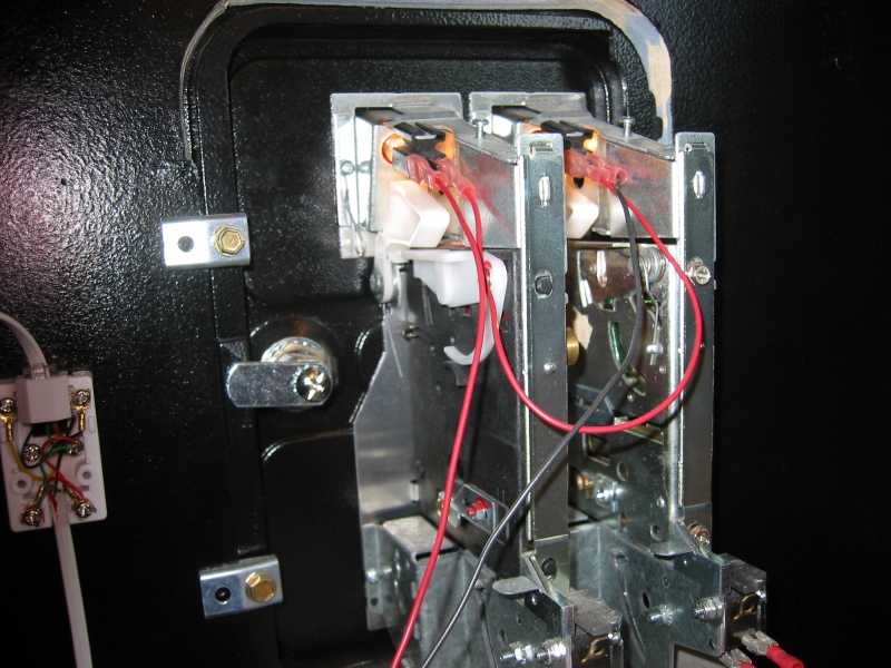
To start with, three lengths of wire were cut. A black length about three feet long (to be safe), a red strip the same length, and another red (or black) strip six-to-eight inches long. Four disconnects and An additional scrap phone cord, with the plug-in at one end, are also required.
Facing as the photos show, attach the longer length of wire, with a disconnect on it, to the left-most terminal prong of the lights. Then place a disconnect on each end of the shorter red wire. Connect to the second prong on the left light, to the left prong on the right light (as in the pictures). Finally, add a disconnect to the black wire and connect it to the last prong. Now you are all set at this end. If this is a bit confusing, just refer to the two pictures below (click for full-screen images).
|
|
|
Now we need to connect the wires to the PC's power supply (Turn off the PC now). This can be done in several ways but I will describe only how it was accomplished on my machine. Note- The following was designed and constructed by a friend- thanks Steve. The descriptions are his.

|
"I started with a standard "Y" power adaptor, I cut the molex off one end (one of the two from the identical side). Then I taped off (whatever colors aren't being used) and stripped back (the two I am using...apparently red and black which must be giving us 12V). |

|
In Version 1.0 (not shown) I took a card slot blank, drilled out a hole and used a surplus headphone jack I had laying about. Red on one post, black on the other. Headphone plug hooked up to the coin door lights, power everything up, plug it in and watch the computer shut it self down. Apparently we were creating some sort of short here.
|


 |
Next I installed the card and connected the molex plugs. |
|
Next, I took the spare phone cord and cut it off so there was about three feet of cord trailing from the connector. Strip back the sheathing on the red and black wires. You'll now tape the red conductor to the red wire coming from the coin door. Do the same with the black. |
|
|
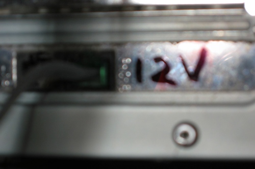
Now the spliced cord, with the phone connector can be plugged into the hacked modem card. Power will now be provided to the coin door's lights. (Note the warning "12V" on the modem card.) |
|

Now you can turn your machine back on. If all went well, you should see the lights glowing.
|
|

Accepting coins

For those times when I wanted an authentic arcade
feel, it was desirable to accept only tokens. This is always fun when
we have people over; it's a kick watching them add tokens to play.
I started by purchasing a standard, small phone jack and a short length of 4 conductor phone cord with the plugs installed on at least one end. I cut about a six foot length of cord and set it aside. This would be the control panel side. I then cut about a three foot length from the remaining cord. This piece would be to wire the coin door itself.
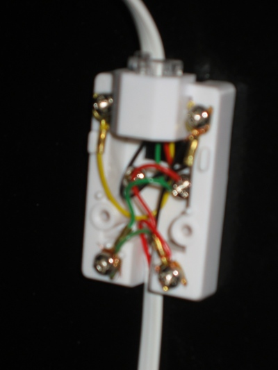
I found a safe location on the inside of the cabinet's door and mounted the phone jack, sans cover plate. I took the second length of cord, stripped the wires, and connected it to the box, as shown at the right.
Next, I determined exactly how much cord I would need to connect to the coin door and cut it to length. Then I stripped this end of the cord in anticipation of attaching the quick disconnects.
|
|

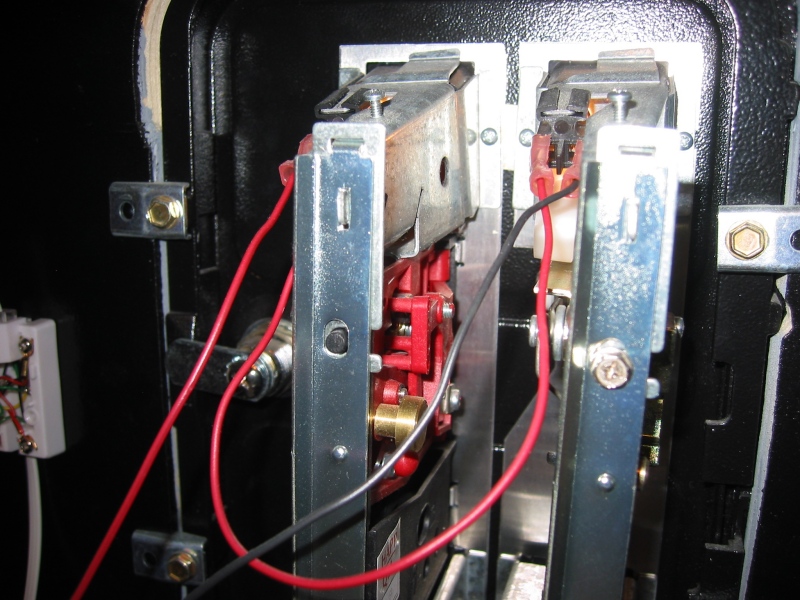
First I attached a disconnect to the red wire and attached it to the coin receptacle on the right (your left as you view the pictures). I did likewise with the green wire to the left coin input.
The ground I did a little differently. I found a bit of scrap black wire and cut a short length (around six inches). I then took the black sire from the phone cord and one end of the scrap wire and inserted, together, into a disconnect terminal. Once crimped, this was attached to the ground on the right (left as viewed) coin ground prong. Then the other end of the scrap wire was crimped into a disconnect and attached to the other ground. Click on the two pictures below to see the completed close-up pictures.
|
|
|


Next I attacked the control panel end. I threaded the cord through the back hole of the controller. Then I stripped the green, red and black wires. I cut the yellow wire back as far as I could as it was not to be used. I carefully inserted the red wire into the Coin 2 input on the IPac and tightened down the screw, being careful to keep the other Coin 2 wire (from the controller button) in, too. Once that was complete, the green wire was inserted into Coin 1 input in the same way. Finally the black, ground wire was inserted into Ground 2 on the IPac and tightened. The entire phone cord as connected to the other controller output cords to keep it from pulling out.
To test the work, I plugged the phone connector into the receiving box on the cabinet door (as show below right), loaded up Pacman, and inserted a coin. The reassuring coin sound met my ears and all was right with the world.
|
Connections to the IPac |
 Connected for input |

A nice bonus to this wiring job is that when the coin door/phone cord is connected, the coin buttons on the controller are disabled so only the coins will drive the games. When I want free play, I just open the cabinet door and unplug the cord. Simple as that.
Hopefully this has helped you a bit. Having a glowing, functioning coin door adds immeasurably to the gaming experience. With a little effort, you can make that happen.