ArcadeCab
Cabinet Plans 2: Control Panel Intro
Table of contents
- Background
- Tools
- Materials
- Cutting Side One
- Cutting Side Two
- Dado for the Base
- Building the Base
- Monitor Shelf
- Ledger Boards
- Speaker Area- Start
- Upper rear
- Back
- Top
- Drawer
- Door
- Speaker Area- Cuts
- Painting
- Assembly
- Marquee
- Monitor Bezel
- List of Boards
- Control Panel Part 1
- Control Panel Part 2
- Wiring the CP
- Attaching the CP
- Finishing Touches
- Software
- Final Thoughts

Control Panel Intro
The next step is the
control panel. I've broken this process into several pages.
This first page will explain how to construct the CP shell. The
next page will detail the drilling of all the holes for the parts, and
the third page gives some explanation how to wire it all up. For
the shell, I used the router, table saw, drill, and jigsaw.
Note- Because Scott is going to paint the control panel base, too, I didn't want any exposed plywood edges on the base's sides, so all four corners are mitered at 45 degrees. This makes the construction a little more complicated than if simple butt-joints were used. There are several more cuts and the measurements of the front and back boards are a little different. Therefore, I have created two distinct sections for the mitre and butt-joints. After that everything is the same with the construction.


Butt-Joints
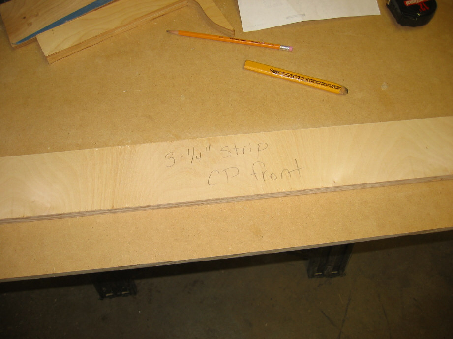
You'll
need one 4" wide strip at least 27" long, one 4" wide strip at least 30"
and one 3" strip at least 30". Take the 27" strip and cut into two
pieces 13-1/2" long. These are the two sides. Take the 3"
and 4" strips and cut at 28-7/8". These will be the front and back
boards. That's it for the butt-joint text.
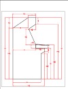
Now you'll begin to create the slope on the two sides. You'll be going from 3" at the front to 4" at the back.
Slope for the two sides
Take one of the two side boards. Measure up 3" on
one end a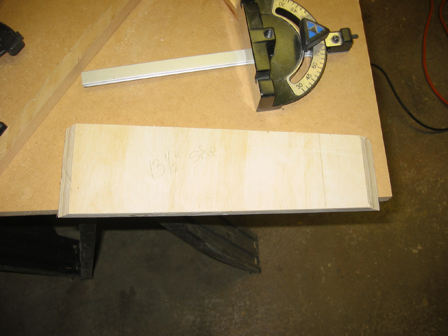 nd
mark the point. On the other end, measure up 4" and mark it.
Draw a line connecting the two points. Take your jigsaw, and using
a straightedge as a guide, cut along the line. Repeat for the
second side. With some sandpaper, smooth any rough spots along the
cut. You should end up with two boards like the one to the right.
nd
mark the point. On the other end, measure up 4" and mark it.
Draw a line connecting the two points. Take your jigsaw, and using
a straightedge as a guide, cut along the line. Repeat for the
second side. With some sandpaper, smooth any rough spots along the
cut. You should end up with two boards like the one to the right.
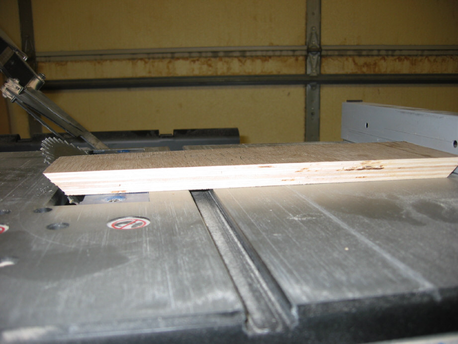
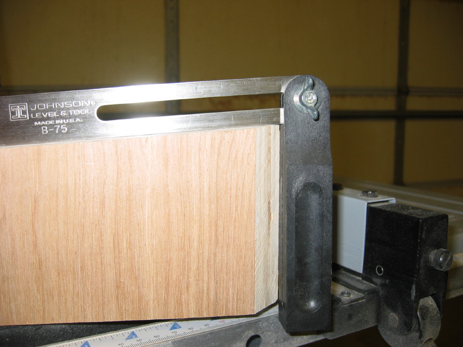
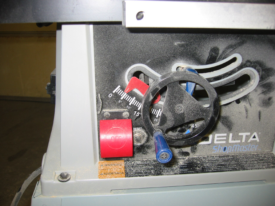
Create the bevel on the top of the front and back
boards
The slope of the sides (one inch from front to back)
necessitates cutting a bevel on the front and rear boards. I
determined the angle by using the handy contraption in picture I
and transferring it to the table saw (J). It ended up being 4
degrees (K).
|
|
|
|

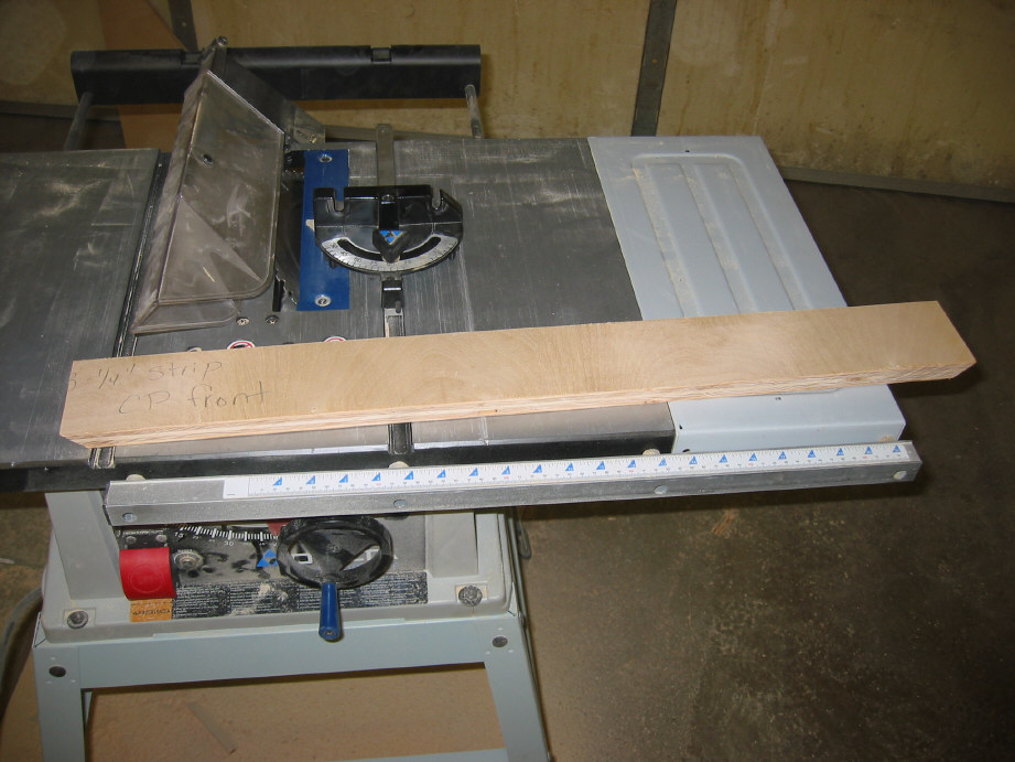
You'll want to now measure up 3/4" on the saw blade and
over 4" for the rear board to determine where to set the fence.
You are essentially trimming off a little bit of wood. Check the
below diagram for what I mean. Once you've made the two cuts (one
for the front and one for the rear board) you are ready to work on the
bottom board.

Base
You will need to cut a piece of plywood for the bottom that
is approx 12" x 28-7/8" (you'll note ours is not exactly that-
use the dimensions you need). We used 3/4" ply because we had plenty
on hand. Feel free to use 1/2" if you want.
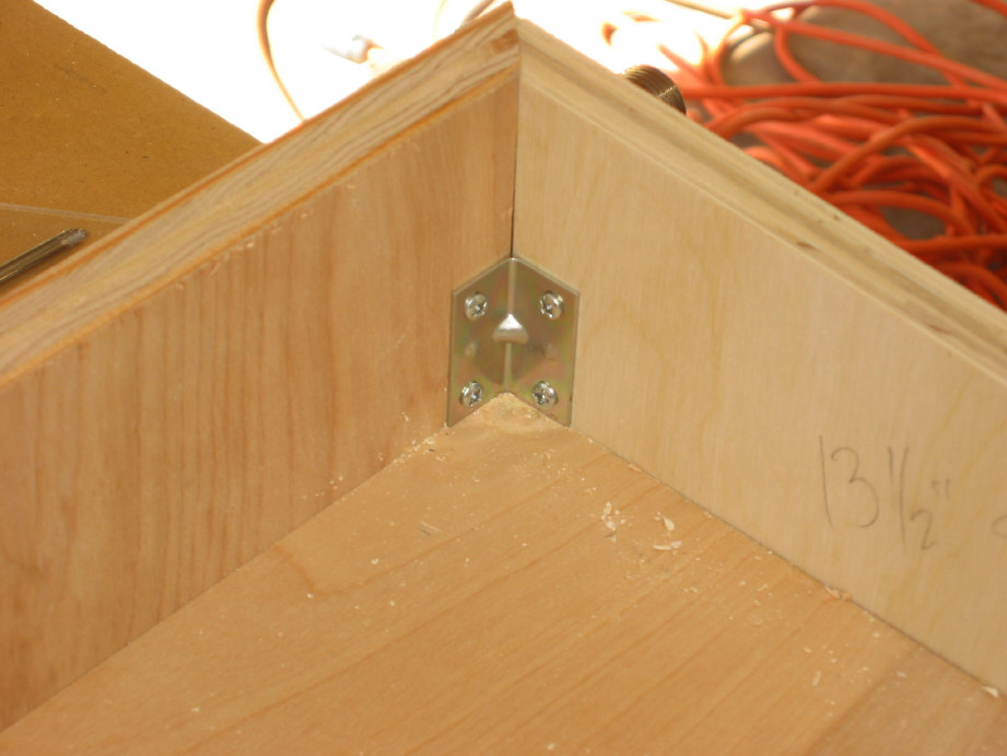
Next you will need to cut some ledgers. I used some scrap 1"x1" pieces and cut them into ledger strips. Now you're ready to begin the base assembly. Lay the plywood bottom on your work surface. Test fit the four sides around the bottom making sure that everything will fit tight when assembled. Get your clamps out and attach them to the box to hold it tight (see L). We cheated and used corner irons (see M) to attach the sides together. We predrilled and screwed one per corner (N). Now you can begin attaching the ledgers as in O and P.
|
|
|
|
|
|
|
|


You should now have a nice box constructed (see Q). Now would be the perfect
time to cut out a hole on the backside of the box to allow the
(eventual) cables to exit. I let Scott determine the location of
the pinball buttons on the side. We did this by having him locate
the proper position by feel and having me mark the center point of the
right side. We then transferred this measurement to the left side. Using a 1-1/8"
spade bit, we drilled the two holes. The method that works
best for me is to start from the outside and drill most of
the way through the board. Then switch and finished
drilling the hole out from the inside. This keeps
splintering to a minimum, and always on the inside if there
is any. Now you are finished with the base for a while.
Set it aside in a safe location. We'll use it a little
later on.
|
|
|
|
|


Top
To begin we cut a plywood board 33" x 16-1/2". In our
situation I already had a template on hand from pervious panel builds.
We traced the outline of the panel, then used a jigsaw to cut close to
the line. Then we clamped the template to the top of our rough-cut
panel, and used a flush-cutter router bit to smooth everything.
If you do not have a template lying around, take your time and draw a
shape on the board that is pleasing to you. You can cut it out using a
jigsaw, following the line closely. Smooth the curves with sandpaper.
Next, you will use the
slotter to cut the T-molding slot. You should remember the process
from when you routed the two cabinet sides, but in case you don't, here
is the text again. You will need to center the cutter in the middle of
the plywood edge. The plywood that I had was seven-ply, so this task was
simple. I adjusted the router height until the cutter was perfectly
aligned with the fourth (middle) layer. I then tested it on a scrap(!)
piece of plywood, snapping a small piece of T-molding into the groove to
make sure it was perfect. Once I decided it was, everything was
tightened down again on the router and the first side was slotted. As
always, move from left to right when using the router (just like reading
a book). I slotted everything except for the bottom. Be careful to keep
the router flat against the plywood surface at all times.
The next page will show you how to make the cuts for all the arcade
parts.
|
|
|

