ArcadeCab
Cabinet Plans 2: Control Panel II
Table of contents
- Background
- Tools
- Materials
- Cutting Side One
- Cutting Side Two
- Dado for the Base
- Building the Base
- Monitor Shelf
- Ledger Boards
- Speaker Area- Start
- Upper rear
- Back
- Top
- Drawer
- Door
- Speaker Area- Cuts
- Painting
- Assembly
- Marquee
- Monitor Bezel
- List of Boards
- Control Panel Part 1
- Control Panel Part 2
- Wiring the CP
- Attaching the CP
- Finishing Touches
- Software
- Final Thoughts

Control Panel II
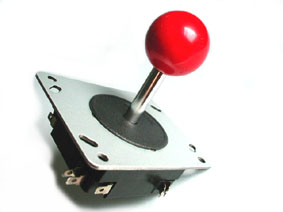
Scott decided on the
following items for his control panel: two Happ 8-way Competition
joysticks, a J-stick balltop joystick, a
GoovyGameGear
Tubospinner,
Template for routing for joystick
I always route out underneath
the control panel for each of my joysticks. This gives them
additional height. For the first time I constructed a template to
make my life a little easier. If you don't feel a need to build
this template, feel free to skip down to the next section on
layout. I
provided this instruction for any interested parties.
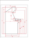
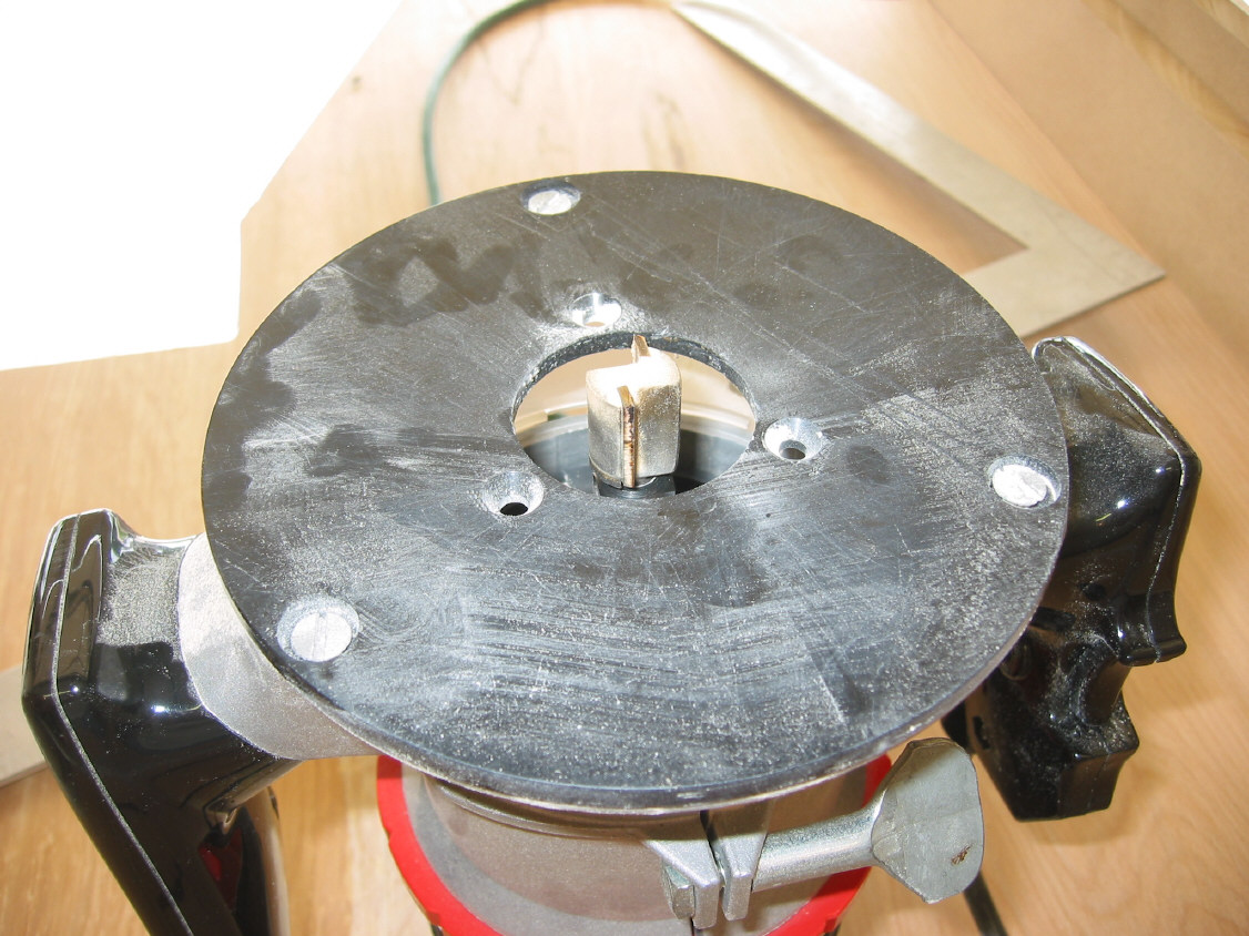
Below is a diagram of how I arrived at the interior template measurements.

Basically what the diagram shows is that I measured from the outside edge of the 1/2" straight bit that is in the router to the edge of the router base plate. A picture of this measurement is to the right. The template will be for the router base to bump into and ride along, so the cut ends up being perfect.
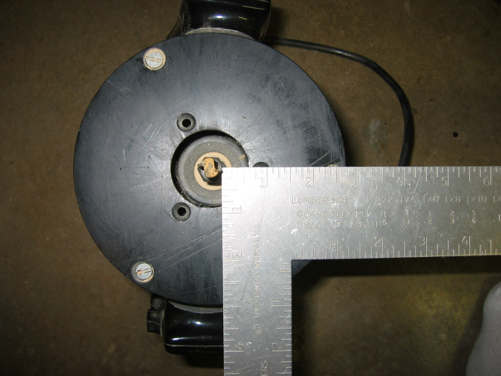
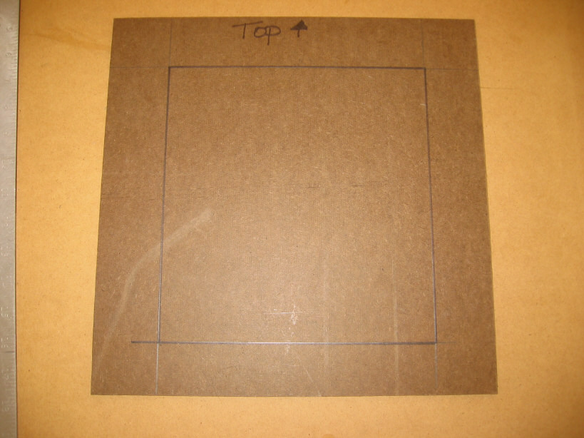
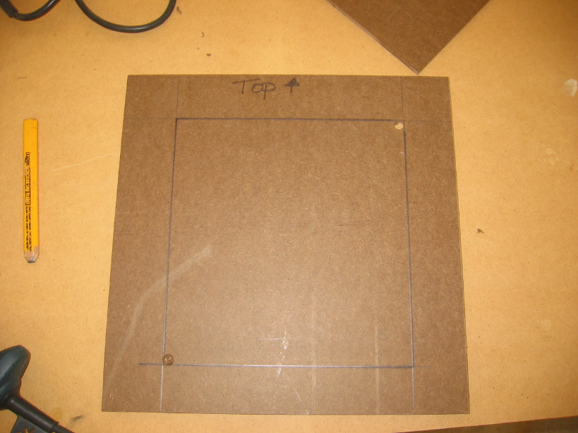
I took a piece of 3/16" masonite (hardboard) and cut a 14" square piece from it (see A). In the middle of the resultant board, I created a square with the measurements from the above diagram (8-3/4" x 9-1/4"), and drew it with a Sharpie (see B). Next, I cut the square out with my trusty jigsaw, after first drilling two holes in the middle (C) for the jigsaw blade to get through initially. Next, I cleaned up the hole with a bit of sandpaper. Now I had the template built and ready to use a little later.
|
|
|
|
|


Layout
You can now take the control panel
top blank you cut previously and layout your controls on it. I'd
recommend first taking the base and lay it atop the panel, just like it
would be placed when attached. Then draw a line around the box.
Remove the box, then draw a box within that box, in one inch.
What this will do is give you an area that is no-man's land- nothing can
be placed where it would touch this line.
The PDF document that I use for the various Happ templates is this trusty one you might recognize from my original control panel page. I do a Select... on each image I need, then print them each out, keeping 100% scale. I then cut these items out with scissors, and tape them to the panel blank. Play around with the layout until you are happy, then take each item down well with a couple pieces of tape.
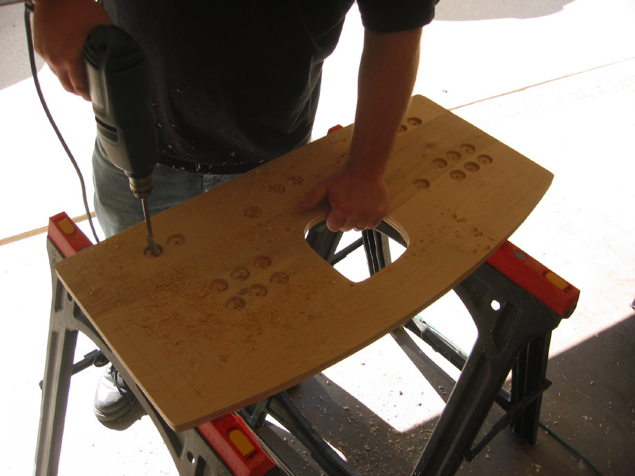
My strategy is to take a drill loaded with my
1-1/8" spade bit
and
slowly start
each button hole. Get it centered exactly right, and
drill down just enough so you'll easily be able to find the hole when
you remove the paper. If you drill too far you'll shred your paper
template, and we don't want to do that quite yet. Do the same with the center of each joystick
hole (for the shaft). Finally, take a 15/64" bit in the drill and start to drill a
hole in each corner of the joystick mounts for the bolts. With a
13/64" bit, do the same with the
four trackball bolt holes. After you've done that, you can remove
the paper pieces (see G) and finish drilling through each bolt hole. You
also drill through the four bolt holes of the trackball template. At
this point you'll have many partially drilled button holes we'll clean
up in a little while.
Trackball hole
Now you are faced with drilling out the
trackball hole.
Drill a few 3/8" holes along the edge of the line you drew (see E). These
will provide you a way of getting the jigsaw blade through. Then
carefully use the jigsaw to follow your line as closely as possible (F).
You should end up with a hole shaped something like G shows.
Note- Although this hole's shape appears goofy, it fits both the Betson
and the Happ trackballs perfectly. Test fit with your
trackball and use the jigsaw to clean up any problem spots. The
trackball should fit snugly.
|
|
|
|


To finish each button hole, drill through most of the way from the front, until the center spike pops through the backside of the panel. Then flip the panel and drill from the backside until you are mostly through. Finally, flip it back good-side up and finish drilling through for all the button holes. This sounds complicated but is obvious once you begin. H through J shows the process.
|
|
|
|


If you have any side pinball button holes like we do, drill them the same way.
Routing the joystick recess
In order to gain a little more
joystick height, you will need to route the under side of the joystick
hole. I will describe how I did it using the template we built at
the top of this page.
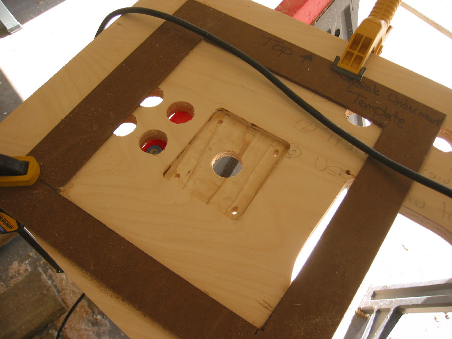
The first thing I do is flip the control panel top over. Take a joystick base, and align it up with the four bolt holes you drilled through the top. Once you have it aligned, use a pencil and draw around the joystick base, then set the joy base to the side. You'll use this pencil box to align the template.
Mount the 1/2" bit in the router (see M). Now set the template down over the box and try to center it. Take the (unplugged) router in the other hand, with the 1/2" bit extended 3/16". You'll need to take the router and align the far right of the bit on the right side line of the box. The outside of the router base will show you where the template should sit. Shift the template as needed. While holding the template in place, move the router to the topside and determine where the top of the template should sit. Recheck the right side. When happy, clamp into place with two clamps (see K).
With the template securely clamped in place, start the router up in the open center hole of the joystick area (simply, the dead center). Take your time, and slowly remove all the material within the lines. The router's base should ride nicely along the template's interior. When done, brush out the dust, and route out any leftover material. Test fit the joystick's base. It should fit snugly, and the bolt holes should line up perfectly. When satisfied, repeat the process with the other joystick areas. It took me less than five minutes per recess.
|
|
|
|
|
|
|


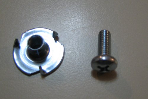
Mounting T-nuts to allow laminate or other covering
My
original control panel has exposed joystick bolts. This is
acceptable for a painted top but you might wish to recess the bolt holes
if you are laminating or covering the panel top at all. Most of my
subsequent projects have been laminated, with hidden bolts.
As Scott was going to use vinyl, we did the same.
You'll need 3/4" T-nuts, a 3/4" spade bit, and 3/16" x 1/2" bolts
to handle
this. For each bolt hole recess, you'll take the spade bit, center
it in the bolt hole from above, and carefully drill down about 1/16".
You may want to practice on a scrap board first.
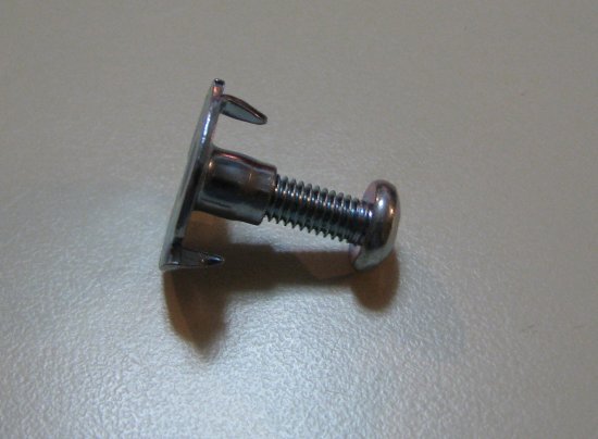
Then you press the T-nut into the hole, and give it a nice little whack
with a rubber mallet (or hammer). The Tee-nut will pull down tight
once you place the joystick base beneath and screw in the bolt snugly.
|
|
|
|
|
|
||
|
|
|
|


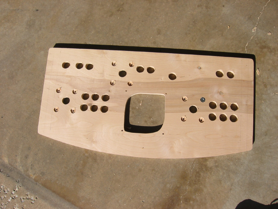
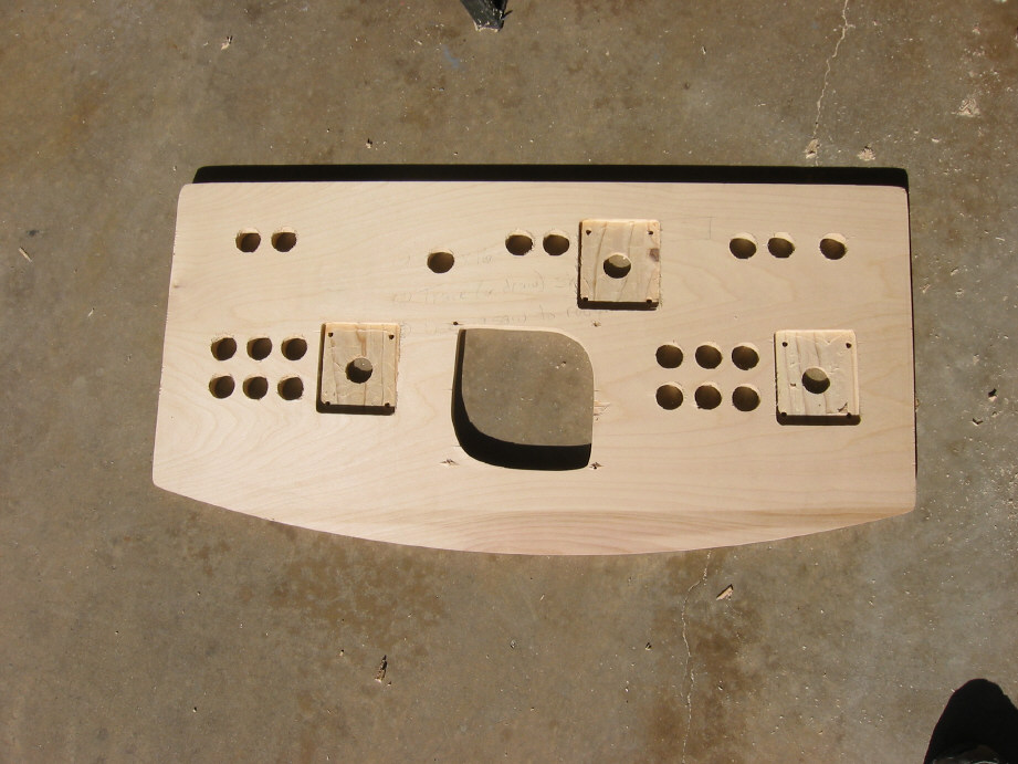
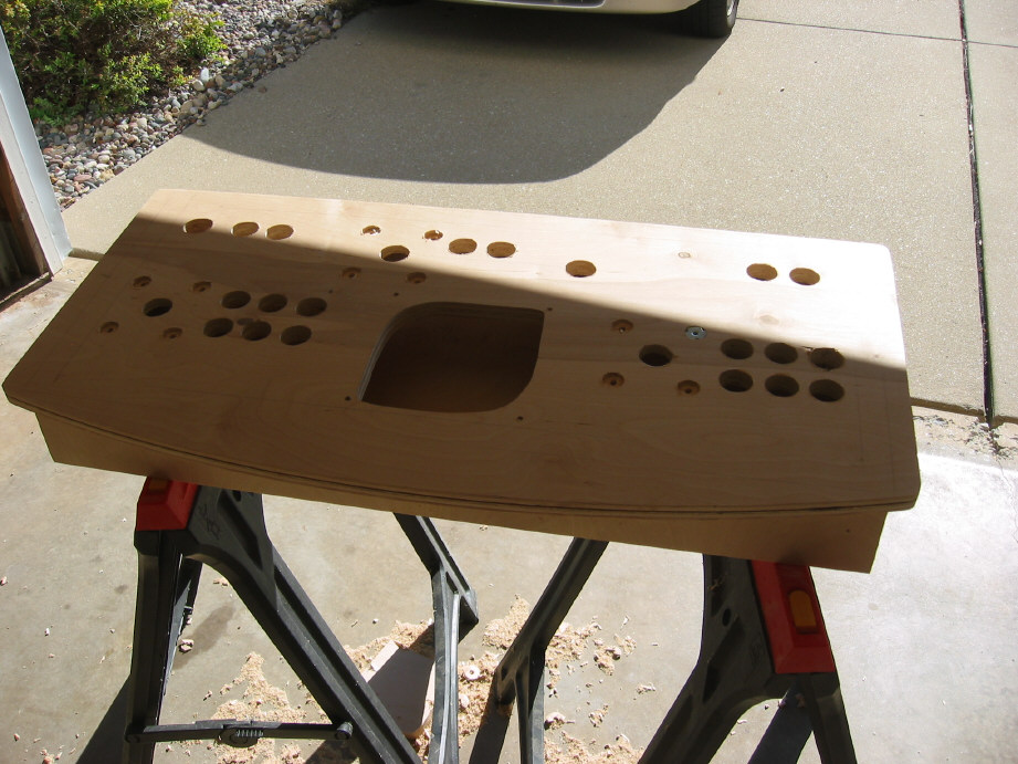
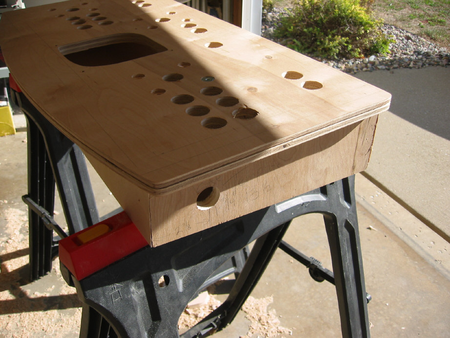
Pictures S thru U show the top with all the holes finished sitting atop the base. It is really looking like something now.
|
|
|
|

Laminating
If you wish to laminate the control panel, I
provide very detailed instructions in my
Ultra-trackball control panel PDF. I won't repeat myself here.
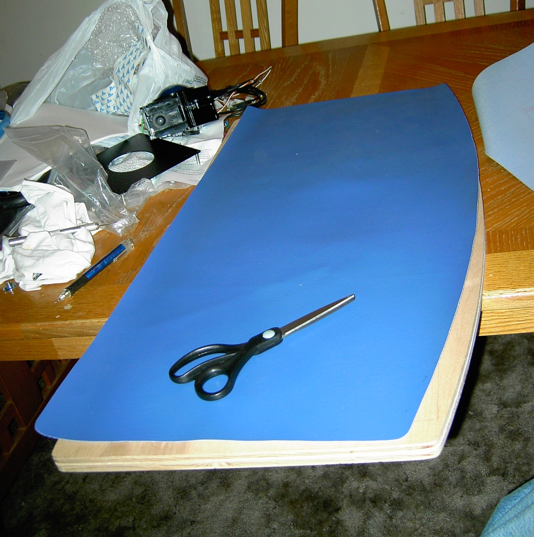
Vinyl
Scott used a heavy-duty blue vinyl that he found at a
local fabric store, of all places. He chose to paint the remainder
of the control panel box, to match the cabinet itself. Refer to
the
Painting
page for details of his painting process.
After everything had tried for a couple days, he began handling the vinyl. (Note- He first attached all the T-nuts and screwed them tight with the bolts. The Tee-nuts now weren't going anywhere.) Scott rough-cut the vinyl to the control panel top (see X). Using an x-acto knife and scissors, he carefully scored and cut out each hole. Once done, he attached the vinyl to the top with adhesive, being careful to align the holes. He used a roller (see 1) to smooth out all the bubbles, moving slowly from one side to the other. He then cleaned up any imperfections, and was ready to attach the hinges.
|
|
|
|
|
|
|
|


Hinges
We just used plain old cabinet hinges to attach the top
to the base (see 2). We placed the hinges on the front edge of the base so
that the top pivots up toward you, so you must go behind to see the
innards.
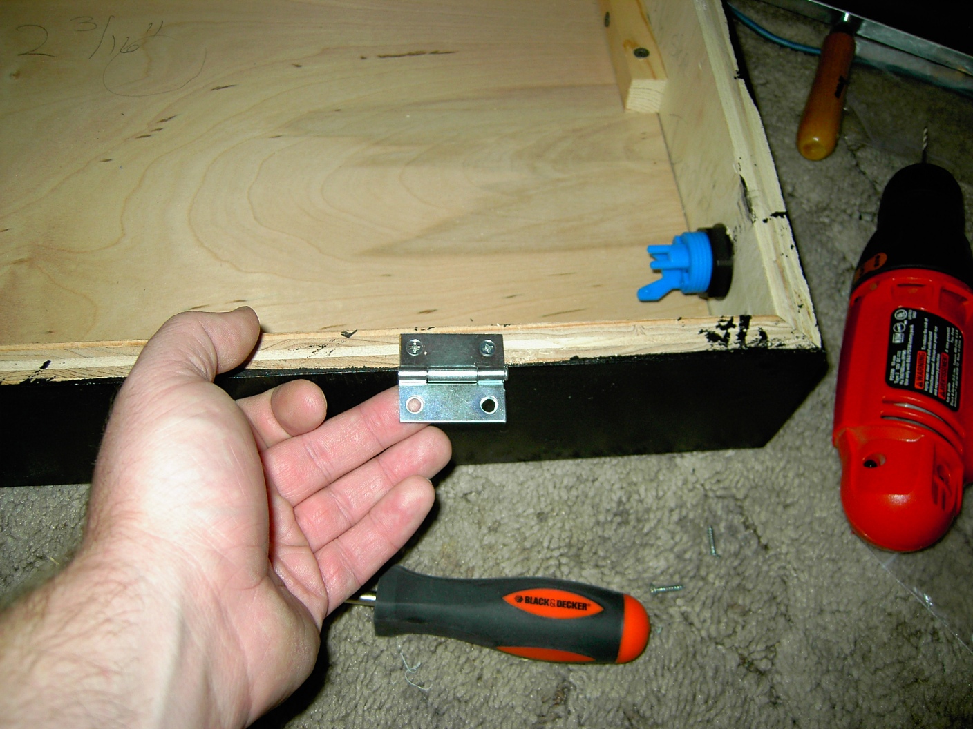
2
Now we can move on to wiring the control panel.