ArcadeCab
Cabinet Plans 2: Wiring the Control Panel
Table of contents
- Background
- Tools
- Materials
- Cutting Side One
- Cutting Side Two
- Dado for the Base
- Building the Base
- Monitor Shelf
- Ledger Boards
- Speaker Area- Start
- Upper rear
- Back
- Top
- Drawer
- Door
- Speaker Area- Cuts
- Painting
- Assembly
- Marquee
- Monitor Bezel
- List of Boards
- Control Panel Part 1
- Control Panel Part 2
- Wiring the CP
- Attaching the CP
- Finishing Touches
- Software
- Final Thoughts

Wiring the CP
Overview
Allow me to start this
page with some basic descriptions of how each step will be done.
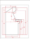
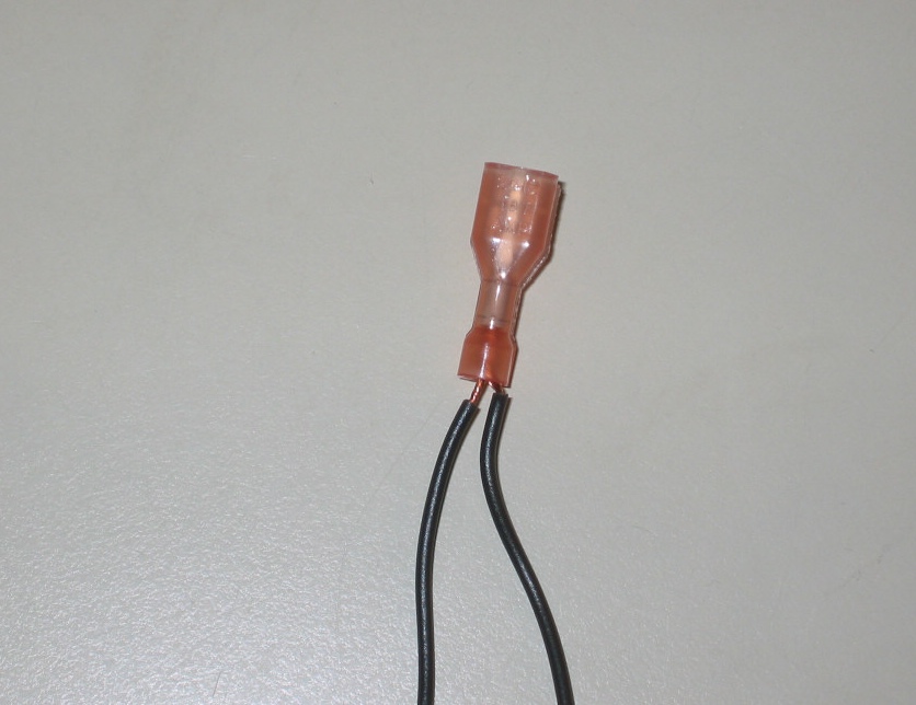
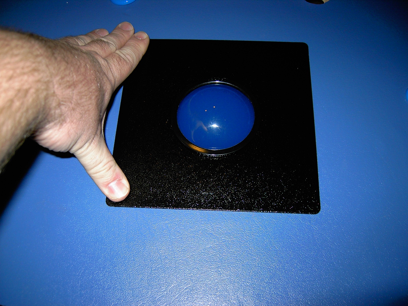
We have used the standard Happ buttons and Competition joysticks in the
control panel. They use a standard Cherry switch, which is wired
with 22 gauge stranded wire inserted into a .187 quick disconnect.
Pictures A through D show each of these items.
|
|
|
|
|
|
|


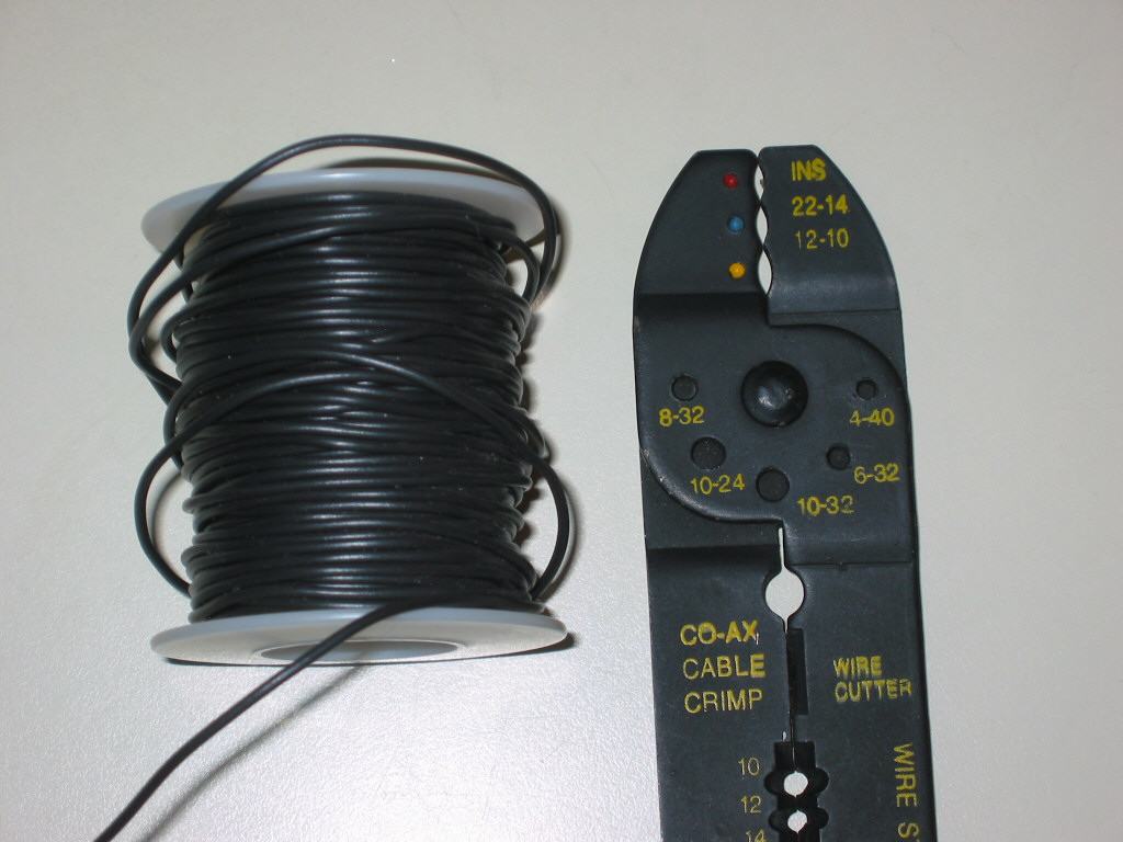
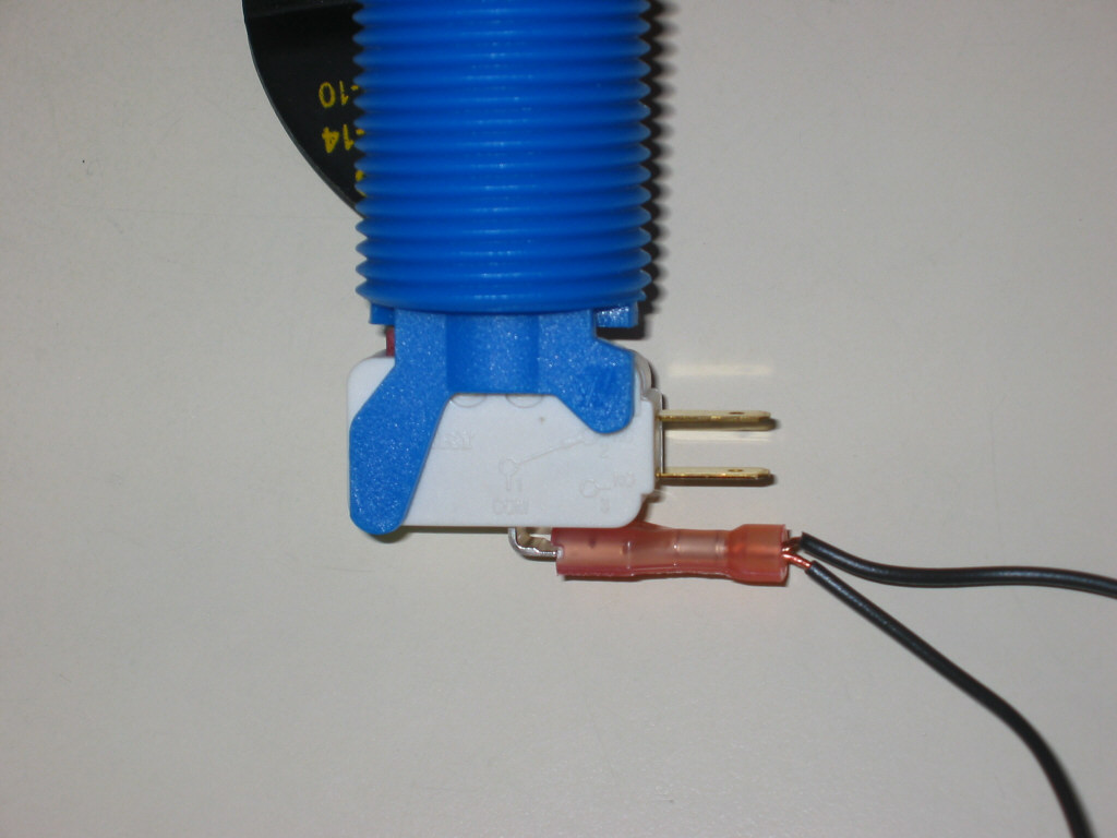
There will be two wires going to each Cherry switch, the unique wire and the common ground. The method I use for the unique connection (where the wire goes directly from the I-pac to the switch) is shown in F through K. I strip off about 3/4" of insulation from the wires end (F) then twist the strands together tightly (G). In order to make the best connection, I double the wire ends upon itself (H), then insert into the disconnect (I). I squeeze the end together so there is no chance of the wire working its way loose. This process has never failed me yet. Finally, connect the disconnect to the Cherry switch (K). Make absolutely sure your connection looks the same as mine does in K.
|
|
|
|
|
|
|
|


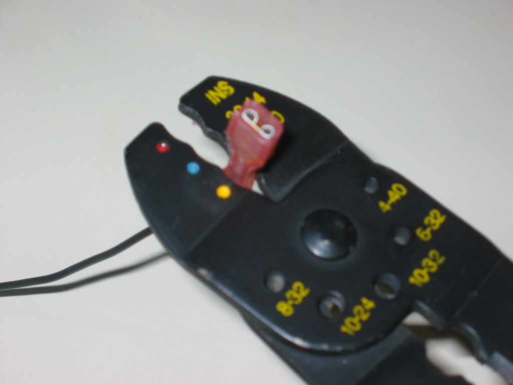

The common ground wire will be daisy chained from button to button, connecting to all the buttons and joystick switches, finally terminating at the ground connection on the I-pac. I take the two wire ends (L) and twist them together tightly (M). I don't double the wires over this time as they are thick enough as-is. Just insert into the disconnect (J) and tighten it with the cutter. Then attach the disconnect to the common ground input on the switch (O). You would do this for each switch except for the very first in the chain. That first switch (the furthest switch from the I-pac) would receive just one wire going into the ground.
|
|
|
|
|
|
|


Wire the panel
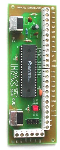
Now that we have covered the basics, we'll start
detailing how to wire the entire control panel. Below is the image
of the Ultimarc I-Pac that we used.
|
|
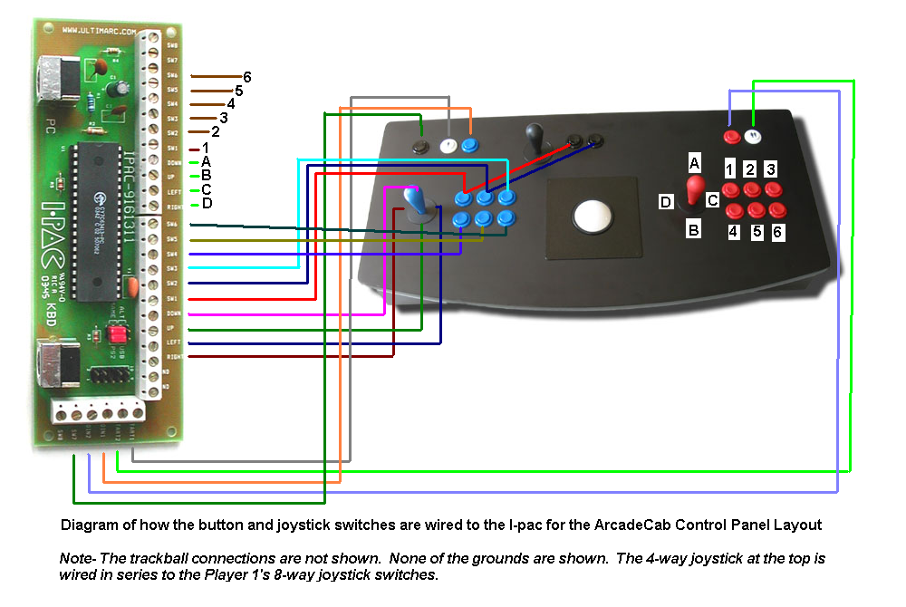
For reference, the next diagram is how the control panel will be connected to the I-Pac. Click on it for the larger, clearer image. Note that I do not show the trackball connections, nor the common ground that snakes from switch to switch. One last item to note is something I left off for image clarity (the lines are hard enough to follow as it is). The switches on player one's joystick are mimicked on the 4-way joy at the top-center. Just like you see the red line going from the I-pac's SW-1 to the control panel button and on to the fire button next to the 4-way's joy, so will each of the four directional switches be. Hopefully that makes sense.
|
|
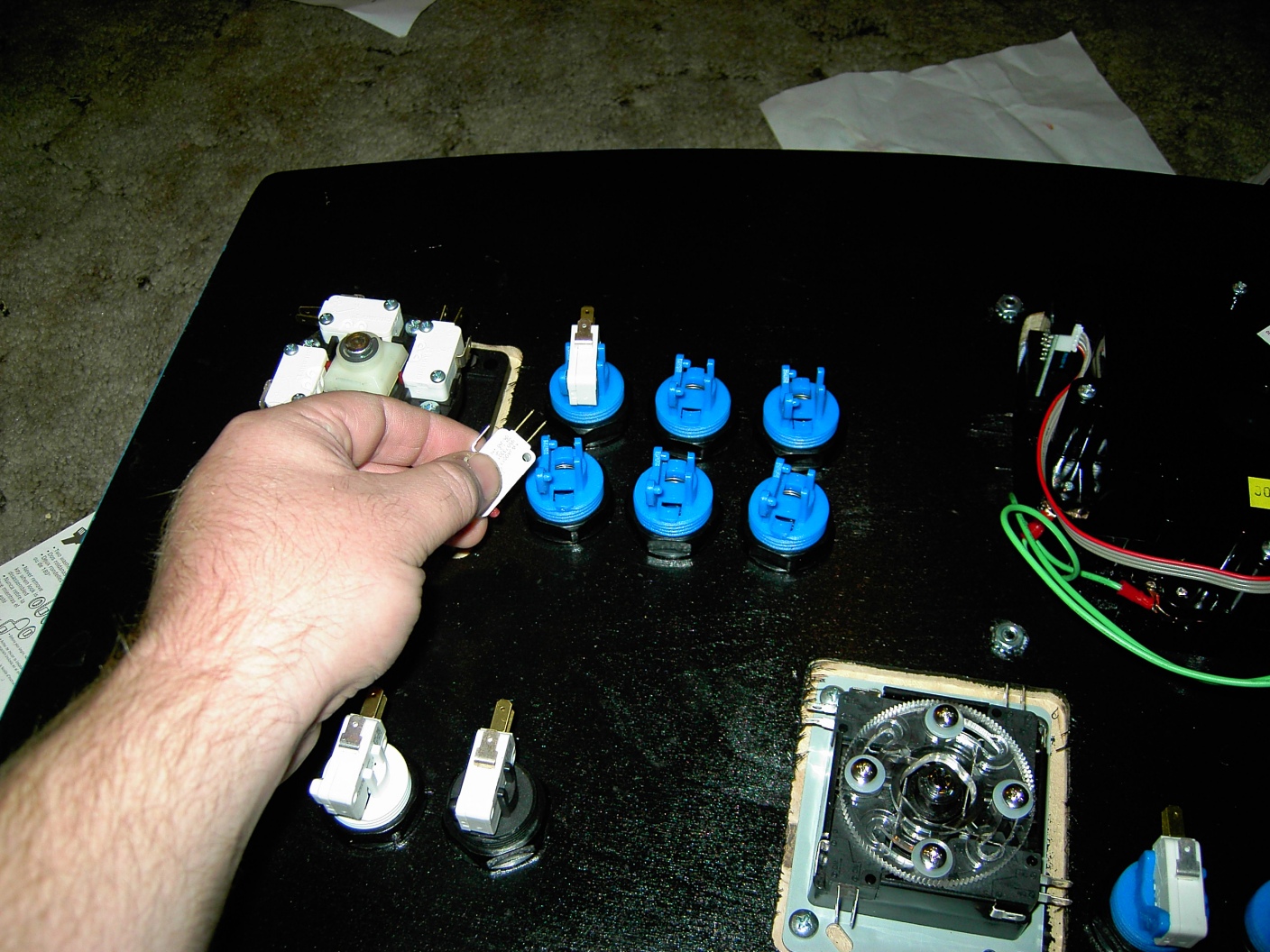
It is usually easiest for you to install all the
joysticks and buttons in the control panel first. Then go around and add
the cherry switch to each button. The joysticks should have come with
the switches installed but if not, install them next.
|
|
|
|

Next, determine where you will place the I-pac. There are several items
to consider when you are determining placement. First is you will need a
location close to the exit hole on the rear of your control panel base.
This is to allow the cable from the keyboard to attach to the I-pac, as
well as allow the cable FROM the I-pac to get out and connect to the
PC's keyboard input. Secondly, you'll want the I-Pac somewhat centrally
located so wire lengths are similar. Lastly, does your control panel's
top hinge open? If it does, you might want to locate the I-pac close to
the hinged side. The reason is when you open the top, the cables from
the keyboard and PC will be pulled inward. The closer you are to the
hinge, the less the cords will be pulled.
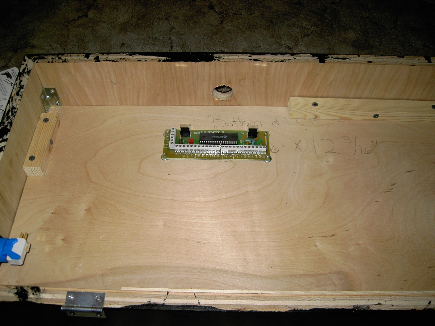
Once you have determined placement, go ahead and mount the I-pac to the
wood. You can either use PCB mounting feet or just simple washers to
elevate the I-pac above the wood a bit (see T). The reason you need it elevated
is that there are solder points on the backside of the I-pac that make
it sit awkwardly. In addition, it's not good practice to put pressure on
these.
|
|
|

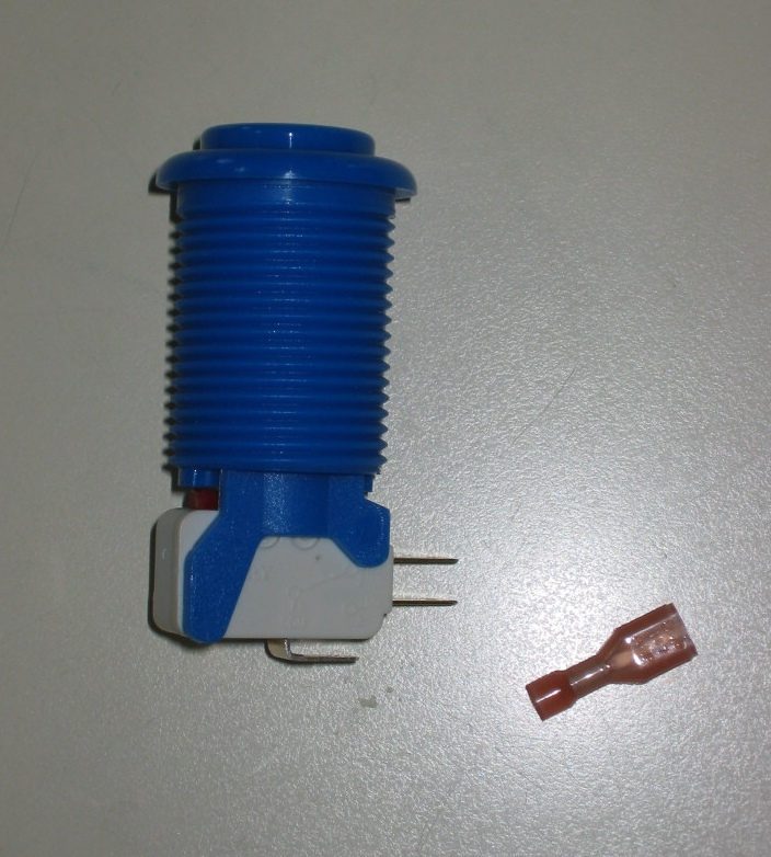
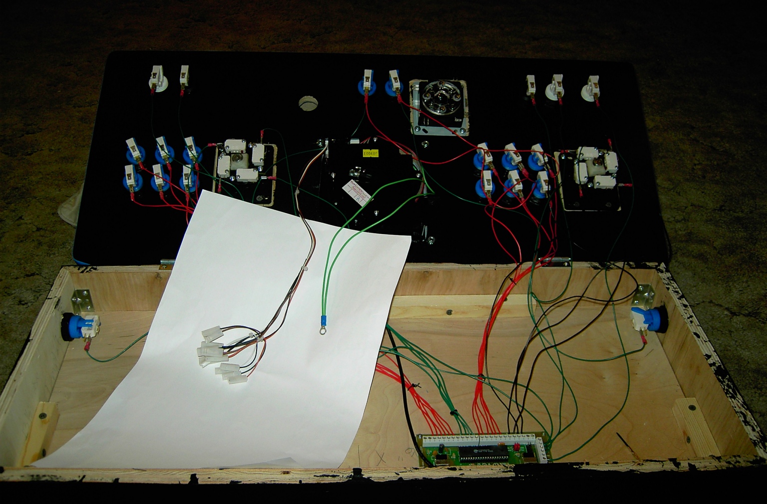
Now that the I-pac has been mounted as in U, you are ready to begin wiring the
panel. Gather your bag of .187 female disconnects and wire cutters (see
D), and your spools of 22 gauge stranded wire. A beer might also be nice
to have at the ready as this will take a little while to complete.
Something important to note is that the joysticks appear to be wired
opposite. When you press right on the joystick, the switch that is
triggered is actually on the LEFT side of the stick, not the right. Same
with the other three directions. Just keep this in mind as you wire.
The steps to wire each switch to the I-pac are as follow:
1) Cut correct length of red wire to get from the I-pac to the switch.
Allow about two to three inches extra to play with.
2) Strip 1/2" of insulation off one end and 3/4" off the other.
3) On 3/4" end, twist the strands, double over, insert into disconnect
and crimp it tight (as in F - J).
4) Insert disconnect onto switch (see K).
5) Insert other end of wire into correct I-pac terminal (see wiring
diagram) and tighten terminal down snugly with screwdriver.
You do this for all the switches. After this is completed, you should be
done with your beer. Go get another cold one as it is time to begin
daisy chaining the common ground. Start at the upper right of your panel
(in ours that is the player two start button). Take the black wire and
cut off a small length, maybe three inches. Strip off 3/4" from both
ends. On one end, twist the strands, double over, insert into disconnect
and crimp it tight (as in F - J). Insert disconnect onto switch (see K).

From now on, all the remaining switches will have two wires going into
them (as in N). You will cut lengths of wire adequate enough to make it
from one switch to the next and attach each wire like shown in L through
P.
The order than I connect the ground switches is shown in the diagram
below. Feel free to wire them however you choose- this ordering just
tends to work well for me. If you have additional buttons, such as side
pinball buttons, feel free to insert them into the ordering where it
makes sense.
At this point, your wiring is almost complete. Attach the cable from
the keyboard into the input on the I-pac, and connect the output cable
to the keyboard-in on the PC.
If you have a spinner, like we did, connect it to the PC. Finally, if you have a trackball, you will need to connect it.
You should be ready to test the buttons and joys. Hook
up the panel to your PC and just test each and every button and joy to
ensure everything is wired up fine. If anything doesn't work, now would
be the time to debug.